

Many of the elements of the Single Line Diagram can be enriched with a detailed functional specification. The functional specification diagram can be accessed from the right-click menu “Open Function diagram”, or by double-clicking the element. As with the Single Line Diagram, the ‘Properties’, ‘Signals’ and ‘Inputs’ views show additional information on the selected element.
The Function Specification Diagram allows the user to
-
Allocate Logical Nodes
-
Group Logical Nodes to higher-level functions
-
Create virtual IEDs
-
Map Logical Nodes to IEDs
-
Select Data Objects and Data Attributes from Logical Nodes to be used for communication purpose (GOOSE, SV, Reports, Command)
-
Specify communication inputs that represent the incoming end of communication link (GOOSE, SV, and report)
-
Specify logical functions
-
Map virtual IEDs to real IEDs
-
Map Specified Logical Nodes and signals to real IEDs Logical Nodes and signals.
-
Edit Data Attributes instance value
-
Handle 61850 flexible naming (functional naming)
-
Add documentation references and text blocks to each element on the drawing.
Anatomy of the Function Specification Diagram
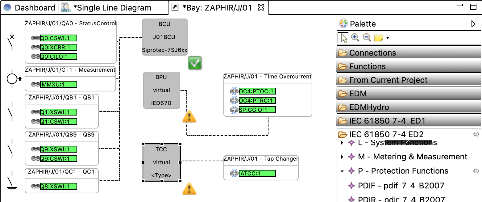
The Function Specification Diagram consists of three different types of elements:
Functions
Functions are represented by white boxes. Their header line displays the functional hierarchy that they are contained in, with the Function name separated by a dash. Functions may be associated to a Conducting Equipment in the same bay - this is both visible in the functional hierarchy at the top of the Function and also as an icon on its left side.
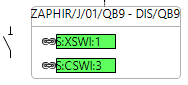
Logical nodes
Logical nodes are represented by green boxes. They are contained in Functions - copying and pasting a Function will also reproduce the contained logical nodes. To the left of each logical node is an indicator that represents the mapping status of the logical node. A closed chain link means that the specification logical node is implemented by (has been mapped to) a logical node in an IED, while a broken chain link signifies the absence of such a mapping.

Virtual IEDs
Virtual IEDs are represented by grey boxes. They do not correspond 1-to-1 to real devices, but are used to create units of functionality that are implemented in the same real device. A virtual IED can be assigned to a real device using the right-click context menu. An assigned virtual IED will have a green checkmark on the lower right, with the name of the assigned IED shown in the center line, and the iedType attribute of the assigned IED in the bottom line. A virtual device can be virtualized again to remove this mapping - in that case, the iedType of the last assigned IED is remembered (see ‘BPU’ in the example diagram)