ESB Helinks STS Training
The training is set to create the substation automation system of an example system based on specifications from ESB. The system is split into essentially two substations: Distribution with 2 voltage levels, Transmission with 1 voltage level. But first, this page shows how the system was created in Helinks according to the information from ESB.
ESB SAS in Helinks STS
Substation | Voltage Level | Bay | IED role | IED type | IED name |
|---|---|---|---|---|---|
ESB Distribution | 38 kV (VDS1) | P11 (Distribution HV) | TCU (Transformer Control Unit) | Siemens A8000 | VSD1P11TCU |
10 kV (VDS2) | C15 (Distribution Incomer) | BPU (Bay Protection Unit) | ABB REF 615 | VSD1C15BPU | |
C13 (Distribution Outgoer) | BPU (Bay Protection Unit) | ABB REF 615 | VSD1C13BPU | ||
ESB Transmission | 220 kV (VTS1) | F1 (Transmission Feeder) | BCU (Bay Control Unit) | Siemens A8000 | VST1F1BCU |
SCU (Switch Control Unit) | ABB REF 615 | VST1F1SCU |
1. ESB Distribution
The single line diagram, function specificaiton diagram, and communication are based on the information which is sent by ESB.
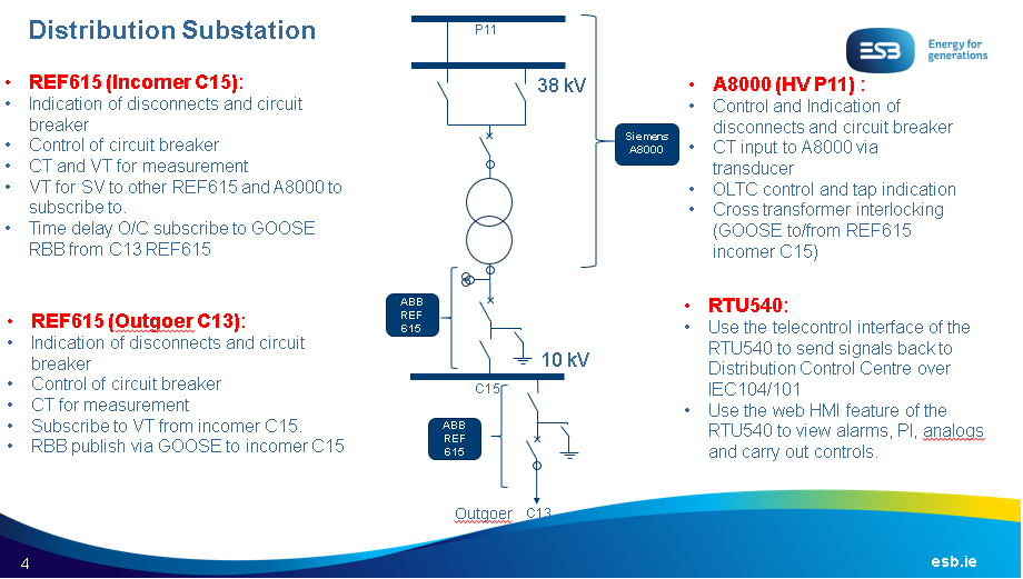
Figure 1: Function and single line diagram from ESB Regarding Distribution Substation
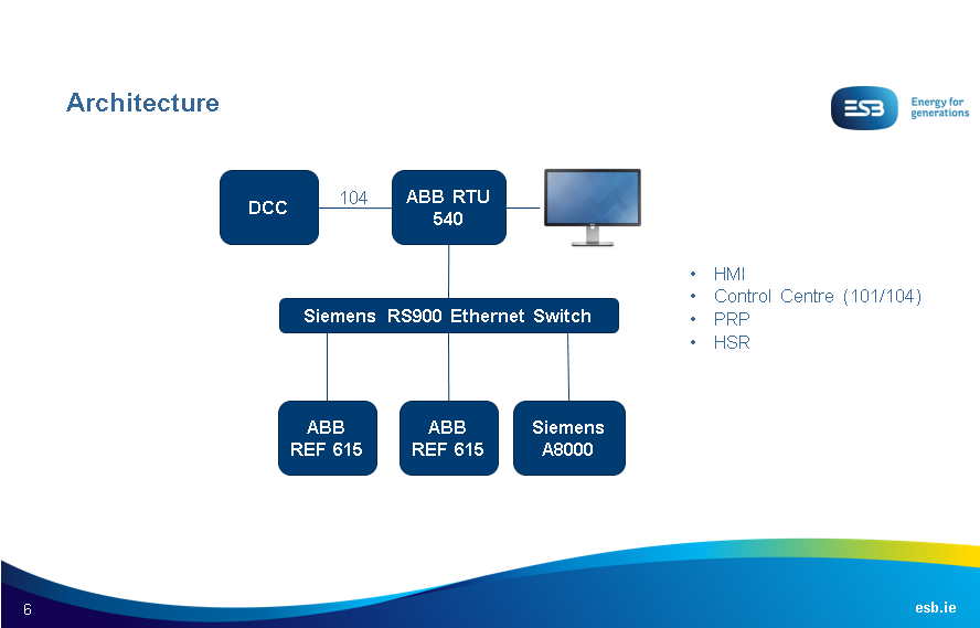
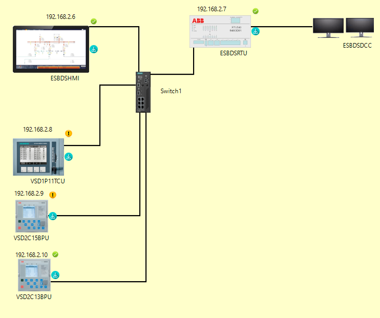
Figure 2: Network architecture for Distribution Substation
The following sections show the translation of the information to the specification and integration which is done in Helinks STS.
1.1. Single Line Diagram
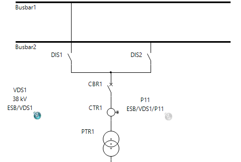
ESBVDS1P11 - Distribution HV
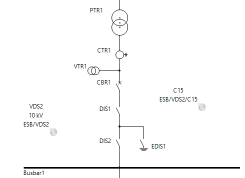
ESBVDS2C15 - Distribution Incomer
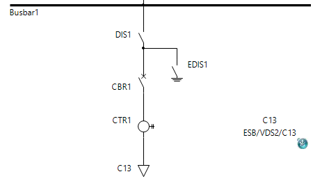
ESBVDS2C13 - Distribution Outgoer
1.2. Function Specification
The following images show the function specification for bays at the distribution substation according to the information from ESB.
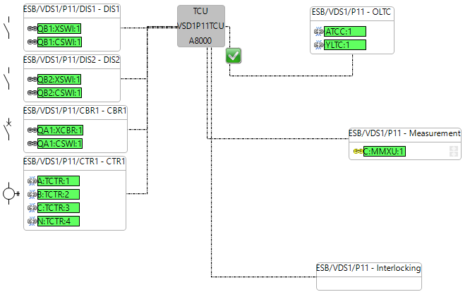
ESBVDS1P11
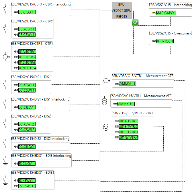
ESBVDS2C15
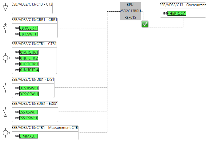
ESBVDS2C13
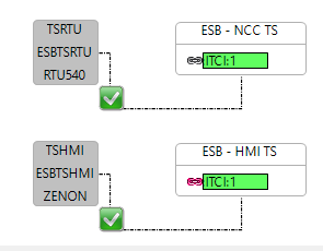
1.3. Communication Configuration
Based on the information from Figure 1, the communication applications which are specified for the distribution substation are created in Helinks STS as the following:
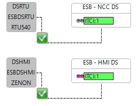
MMS Client Server Application
Signals from the bays are routed through Interface logical nodes to the distribution HMI (Zenon IED) and RTU (ABB RTU 540). In Helinks STS, this is done in the substation function specification diagram.
GOOSE Application
Based on Figure 1, GOOSE applications for the distribution substation are created as the following ones in Helinks STS.
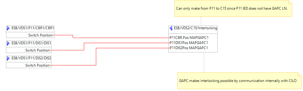
DS Transformer Interlocking
Between P11 and C15.
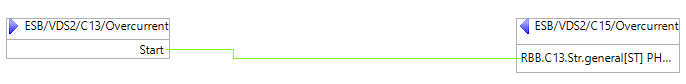
DS Reverse Blocking
Between C15 and C13
SV Streams
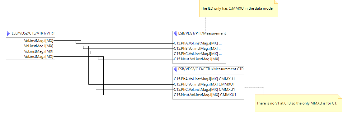
Between C15 and C13 and P11. Voltage values are being streamed.
1.4. Network Diagram
Based on Figure 2, the network diagram for the distribution substation is created in the Helinks STS System Diagram as the following. The IP addresses are chosen by Helinks STS since no information regarding them was given by ESB. The IP table is the following:
IED name | IED manufacturer | IP address |
|---|---|---|
VDS1P11TCU | Siemens A8000 | 192.168.2.8 |
VDS2C15BPU | REF 615 | 192.168.2.9 |
VDS2C13BPU | REF 615 | 192.168.2.10 |
ESBDSRTU | ABB RTU 540 | 192.168.2.7 |
ESBDSHMI | Zenon | 192.168.2.6 |
Important note about the modeling decisions:
Some functions could not be applied based on the information from ESB because of the lack of availablity of logical nodes in the IEDs. For instance, the cross interlocking GOOSE applciation between C15 and P11 should be the transmission of switchgear positions to a generic logcial node (GAPC) which is internally communicating with the CILO at each bay. However, the bay P11 could not have this logical node because it does not exist in the IED data model. So, the Interlocking function is created for P11 but it is empty. The other example is OLTC tap indication and control which is covered by the logical nodes ATCC and YLTC but again, these do not exist in the P11 IED from Siemens and so the logical nodes are not mapped.
The voltage transformer values are sent from C15 to C13 and so C13 has to receive them in an MMXU logical node which is associated with a VT. However, this bay does not have a VT and so the C:MMXU which is shown for the specification for C13 is the subscriber to this information.
2. ESB Transmission
The information from ESB show how this substation only has one bay.
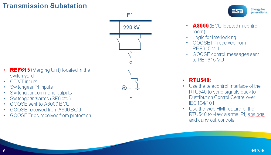
Figure 3: Information from ESB Regarding Transmission Substation
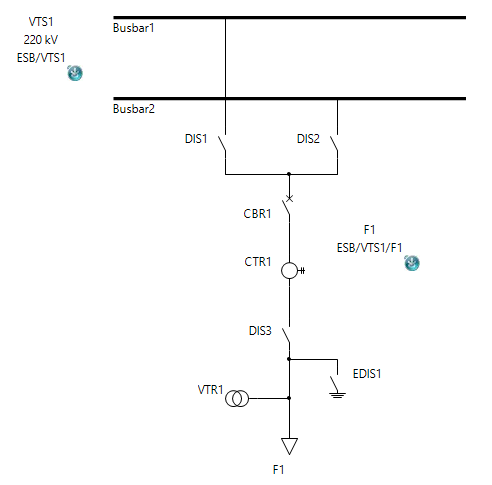
2.1. Single Line Diagram and Function Specification
ESBVTS1F1 - Transmission Feeder
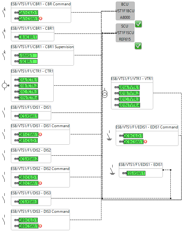
Function Specification Diagram
2.2. Communication applications
MMS Client Server Application
Like the configuration for the distribution substation, the signals from the bay are routed through the interface logical nodes to the an HM (Zenon) and RTU (ABB RTU 540) in the substation specification diagram in Helinks STS.
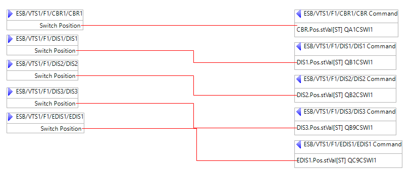
GOOSE Application
From Figure 3, the following applciations are created in Helinks STS.
TS Control
Signals from switchgear command functions (OpOpn and OpCls) from BCU IED are sent to the switchgear from SCU.
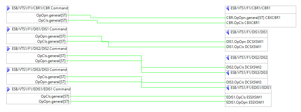
TS PI
Indications sent from the switchgear functions from SCU to the switchgear command functions from BCU.
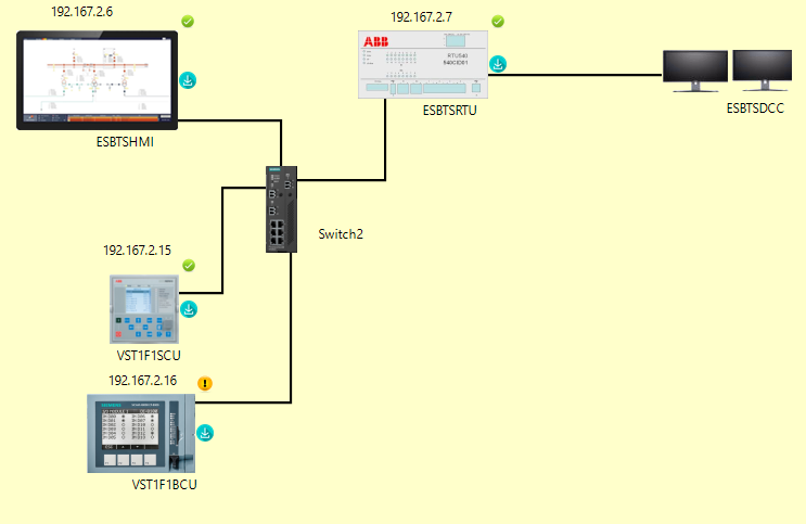
2.3. Network Diagram
There is no information from ESB to show the network diagram for the transmission substation. However, from the Distribution information, it is implied that the network diagram for transmission could also be similar. The IP address of the IEDs are according to the following table.
IED name | IED manufacturer | IP address |
|---|---|---|
VTS1F1SCU | REF 615 | 192.167.2.15 |
VTS1F1BCU | Siemens A8000 | 192.167.2.16 |
ESBTSRTU | ABB RTU 540 | 192.167.2.7 |
ESBTSHMI | Zenon | 192.167.2.6 |
So, it looks like the figure below from Helinks STS.
Important note about the modeling decisions:
According to Figure 3, the BCU IED which is A8000 is set in the control room and so the Command functions are assigned to this IED. On the other hand, the REF 615 is called SCU which handles both the instrument transformers as a Merging Unit and PI signals from switchgear.
The switchgear command functions should include signals that show how the switchgear are being opened or closed which means they should logical nodes such as CSWI which include signals such as OpOpn and OpCls from IEC 61850 - 7- 4. However, the CSWI logical nodes from the A8000 IED which is in charge of control signals according to Figure 3, does not have those signals. So, the signals are specified and are not mapped and so the GOOSE application “TS PI” and “TS Control” cannot be configured.
Training Guide
The training is split into 4 sessions, each covering an aspect of the SAS of the ESB Distribution and Transmission and to reproduce the results which are shown in this page.
The following links are to each session of the training.