Session 1
This session is make you familiar with the single line diagram design in Helinks STS and creating functions for a bay in function specification diagram. Your starting point will be a blank workspace and you have to fulfill the following objectives.
Objectives
Design the substation structure of the ESB substation and add a breaker for a bay.
Create one function for a bay
Workspace: WS1
Single Line Diagram
What you create in Single Line Diagram are the following:
Substation | Voltage Level | Busbar | Bay | Equipment |
|---|---|---|---|---|
ESB | VDS2, 38 kV | Busbar 1 | C15, Incomer Bay | Circuit Breaker CBR1 |
From the Helinks STS dashboard, click on the “Single Line“ option.

The workspace is empty so you don’t see anything on the space. On the right hand side of the screen, you can see the palette which is used to design the single line diagram of the substation.
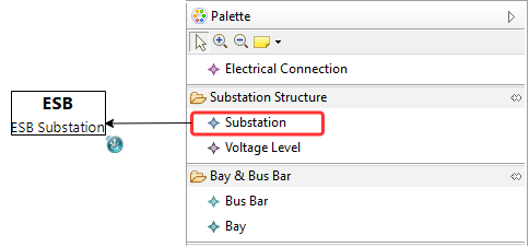
From the “Substation Structure“ tab, click on “Substation“ and click on the screen to create the substation class. Use the name “ESB“. Click on the description and write “ESB Substation“ if you want.
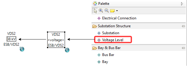
From the same Substation Structure, click on “Voltage Level” and click on the screen. This is the lower voltage level of theESB Helinks STS Training so call it VDS1 and set the voltage level to 38 kV by clicking on the field and writing the number.
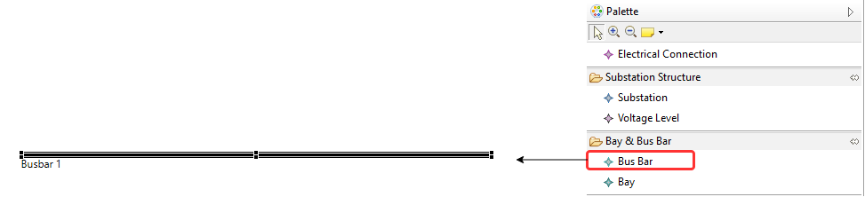
From “Bay and Bus Bar“ tab, choose “Bus Bar“ and draw a line on the screen. The name can be Busbar 1.
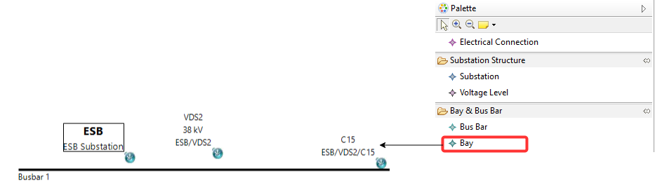
From “Bay and Bus Bar“ tab, choose “Bay“ and click on the screen. Choose the name “C15“. This is the ESB Helinks STS Training .
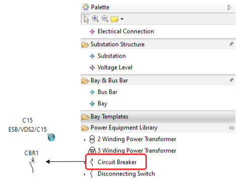
The Substation Structure is completed. Click on C15 and make sure it is highlighted. From “Power Equipment Library“, choose “Circuit Breaker“ by clicking on it and click on the screen. Choose the name “CBR1“ for the circuit breaker.
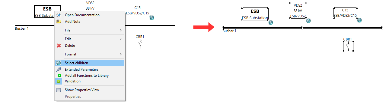
Use the right mouse click on C15 and choose “Select Children“. This way, you can see the CBR1 highlighted. This means CBR1 is part of C15 so you have created the structure correctly. For further verification, you can choose the same option on VDS2 and ESB substation.
Achieved Goals
Created substation strcuture
Created a power equipment for a bay
Function Specification Diagram
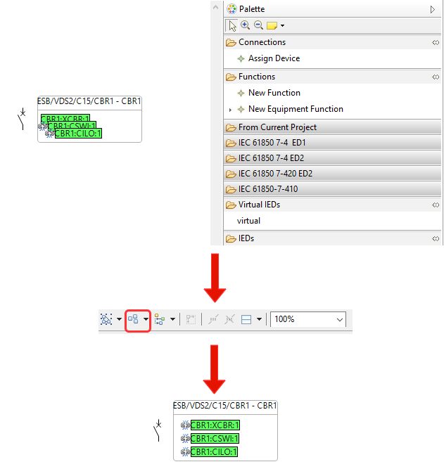
To open the function specification diagram of a bay, double click on “C15“. It should open a new window with a box with green logical nodes inside. This is the equipment function assigned to CBR1 which is done automatically by Helinks STS. On the right hand side of the screen, you should see the palette which consists of IEC 61850-7 logical node libraries, virtual IED creation, Function creation and assigning IEDs to functions. You can click on the “Arrange All“ option at the top of the screen to arrange all icons.
For this bay, there is a new function needed. It is the overcurrent function which will play a role in reverse blocking transmission between C15 and the outgoer bay C13.
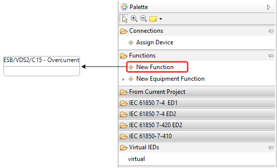
From “Functions“, choose “New Function“ and click on the screen to create a box. Write the name “Overcurrent“.
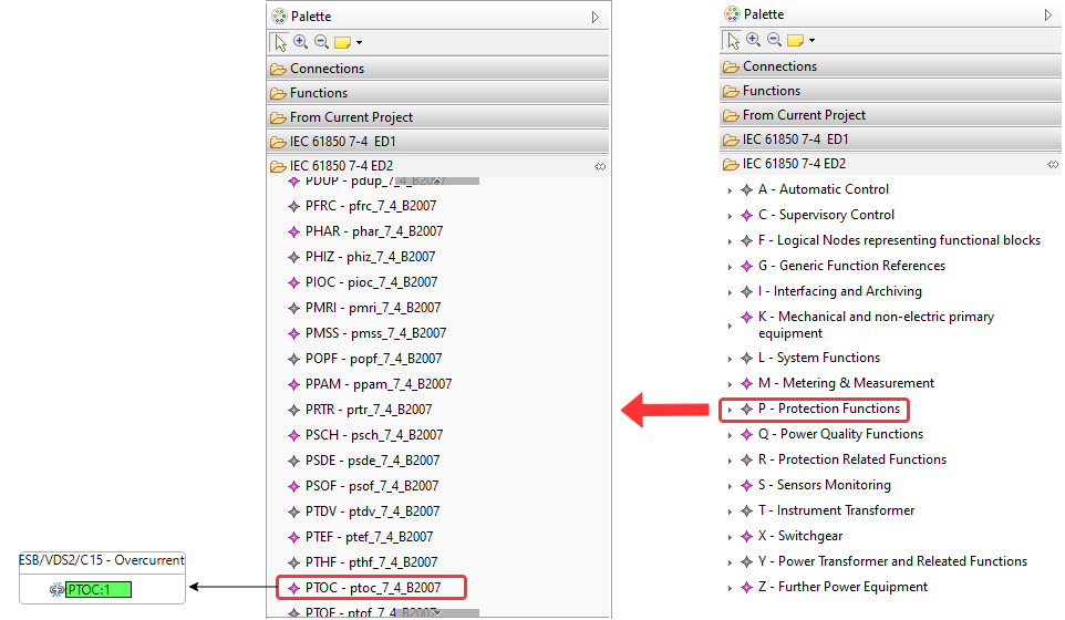
We need the overcurrent logical node. Open “IEC 61850 7-4 ED2“ and choose “P - PTOC” node. Then click on the inside of the Overcurrent function to add the logical node to the function.
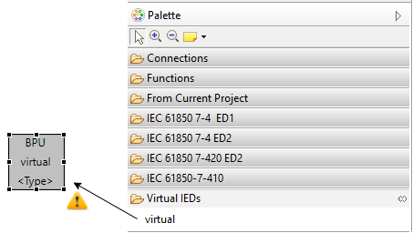
From “virtual IEDs“ tab, click on “virtual“ and click on the screen to create a virtual IED. Choose the name “BPU“ as the name of the virtual IED.
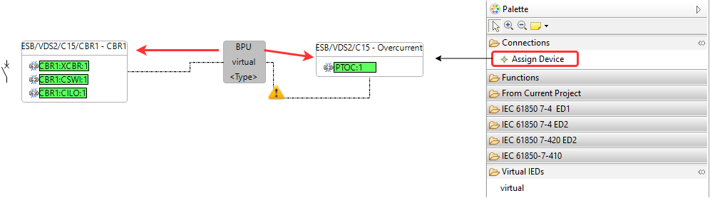
From “Connections“ tab, click on “Assign“ and draw a line from BPU to Overcurrent and another line from BPU to the function for CBR1. This assigns the IED to different functions.
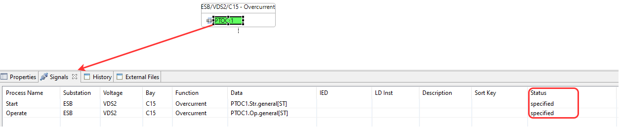
Click on PTOC or either of the logical nodes for CBR. You can delete these logical nodes or add new ones to their functions. Once you have clicked on PTOC, look at the “Signals” tab on the bottom of the screen and you can see the signal name, the IEC 61850 address and the signal status which is “Specified“ as the time being.
Achieved Goals
Created a function in function specification diagram for a bay.
Added logical node.
Created a virtual IED and assigned it to the function.
Finished specification for a bay.