Session 3
The session is to make you familiar with IED implementation and communication configuration.
Objectives
Implement the IED BPU for the bay C15.
Map the logical node PTOC to the one from the IED data model.
Configure communication.
Workspace: WS3
WS3 contains the full System diagram for the IEDs which are imported and the communication applications are specified.
IED implementation
From the Dashboard, open Single Line and the function specification diagram for the bay C15, as you have learned from Session 1 .
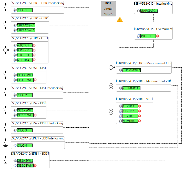
You can see from the picture that the bay contains multiple functions including the Overcurrent one which you created in Session 1.
Use the right mouse click on the IED and choose “Implement“. You will see a window showing all the IEDs which are instantiated and part of the workspace. Choose the IED VDS2C15BPU.
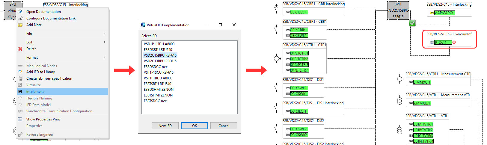
You can see that almost all of the logical nodes are already mapped to this IED. PTOC is not mapped, so double click the left mouse button on the green check mark next to the IED to open the mapping display for this IED.
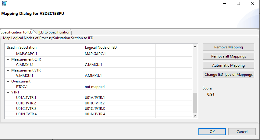
The window which opens is the mapping display. You can either use the “Specification to IED“ tab to map the logical nodes that are specified in the system to the ones from the IED data model or you can use the “IED to Specification“ to map logical nodes from the IED data model to the specification in the system. This can be used when logical nodes are not specified before.
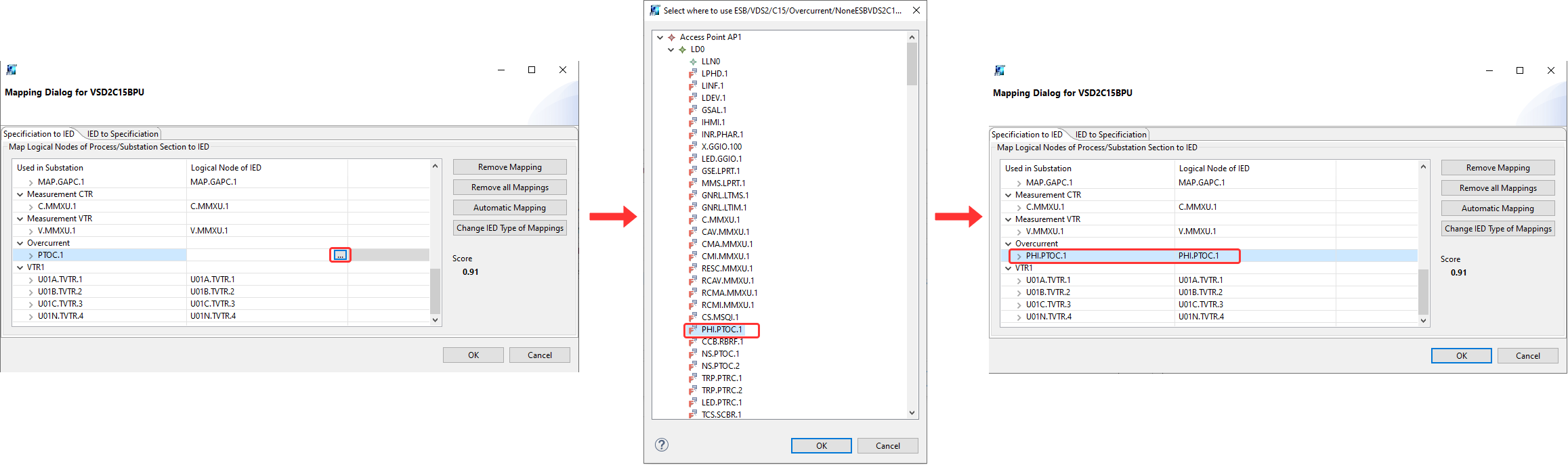
In the IED data model, stay in “Specification to IED“ and find the Overcurrent function and the PTOC logical node. Click on the space under the column “Logical Node of IED“ for PTOC and click on the three dotted icon.
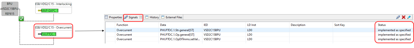
The window which opens is all of the logical nodes in the IED data model. Find the logical node “PHI:PTOC:1“ which is the instantaneous overcurrent logical node but also has the time delay component. Press OK and the logical node should be mapped.
Check the Signals tab on the bottom of the screen to notice how the signal status is changed for PTOC from Specified to “Implementation as Specified“. Also the logical node has taken the prefix of the logical node from the IED data model.
Communication Configuration
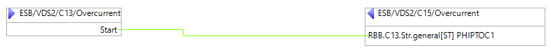
Communication applications are already specified and you can check out the Reverse Blocking application to notice how the application also shows the prefix of the subscriber IED for PTOC.
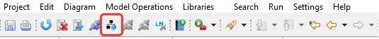
At the top of the window, find the icon called “Set SCL communication settings from specification“.
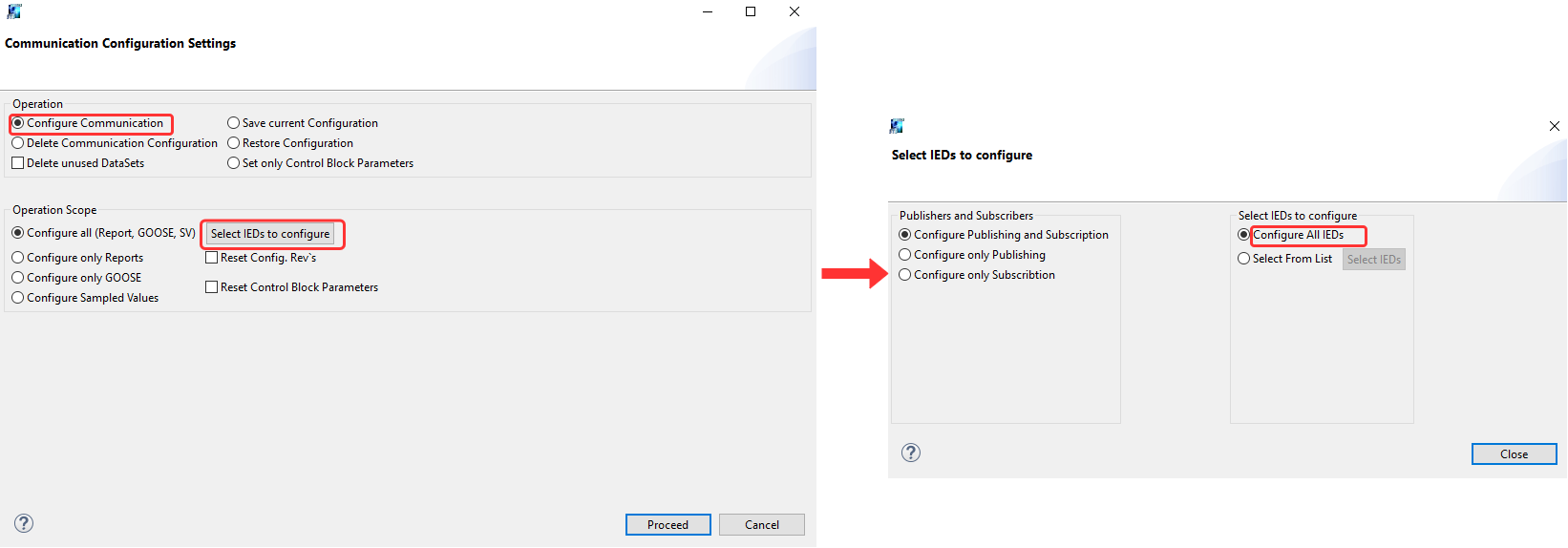
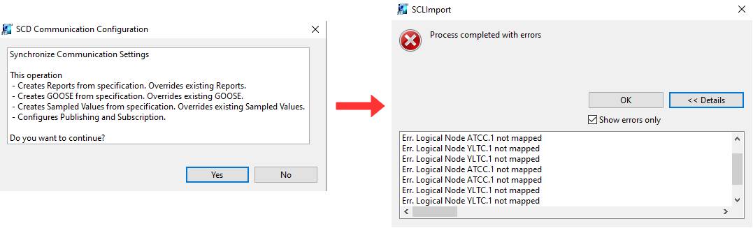
Click on the icon and you can see another window. It shows the options for communication configuration. You can either save what is already configured, delete it, or configure from scratch. Choose “Configure Communication“. Then choose “Select IEDs to configure“. The next window lets you choose some IEDs you wish to configure or to select all of them. Choose “Configure All IEDs“.
Another window opens to ask for verification of configuring communications. Press OK. Another message will show if the configuration was a success or not. If there are errors, you can click on the option “Show Errors“. Usually the errors are related to logical nodes which are not mapped which exist in this workspace.
So now the communication is configured and session 3 is done.
Achieved Goals
Implemented IEDs to virtual ones.
Mapped logical nodes.
Configured communication applications.
Session 4 is to verify the communication configuration and to view the library.