Session 2
This session makes you familiar with communication specification for a Substation Automation System, and first steps of integration which are importing IEDs and instantiating them to the worikspace.
Objectives
Specify a GOOSE communication application.
Import an ICD file to the workspace
Instantiate two IEDs to the workspace
Workspace folder: WS2 - ESB
The workspace contains the complete single line diagram and function specification for all bays. So, before moving to the guide, take a few moments to look at the bay C15 single line diagram and function specification diagram and also other bays.
Communication Specification
The communication application which you will create is a GOOSE application called “Reverse Blocking“.
You can see how the application should look like after completion in Helinks STS in GOOSE application Reverse Blocking.
The communication applications can be created using the “Applications“ option from the dashboard.

Move on to GOOSE tab and you should see there are already some applications which are created here.
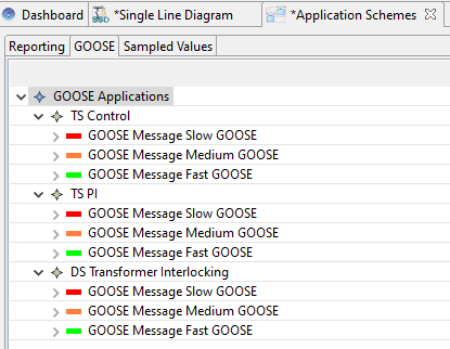
The colors indicate the priority of the message. Green is for fast GOOSE messages, Orange is for medium ones, and Red is for slow messages.
Use the right mouse click on the “GOOSE Applications“ heading and choose “New Application“. Write the name “Reverse Blocking“ as the name of the application.
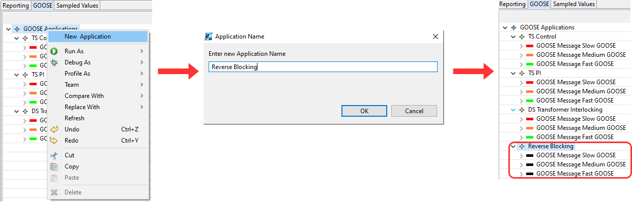
As you can see from the figure, the priority of the GOOSE message are set to colors yet.
Use the right mouse click on “GOOSE Message Slow GOOSE“ for Reverse Blocking and choose “Set Connection Color“. Choose Red for this connection. Do the same process for Medium and Fast messages and choose Orange and Green, respectively. You can look at the picture below as the reference.

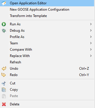
Use the right mouse click on “Reverse Blocking“ and choose “Open Application Editor“. You should see an empty space. On the right hand side, you can see the palette which can help you create publishers and subscribers and draw a link between them using slow, medium, and fast GOOSE which are now set to their respective colors.
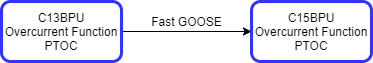
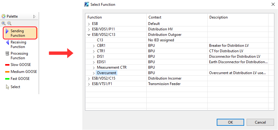
On the right hand side, you can see the palette which can help you create publishers and subscribers and draw a link between them using slow, medium, and fast GOOSE which are now set to their respective colors. Choose “Sending Function“ and click on the empty screen. This will help configure the publisher. A window opens and asks you to choose a function. Since the publisher is C13 Overcurrent, find it and choose that function.
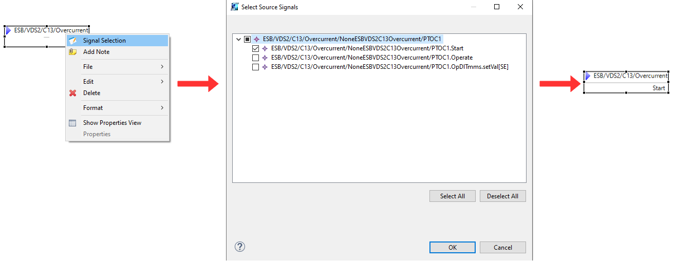
Next step is to specify the signal which is being published. Use the right mouse clock on the C13 Overcurrent function and click on “Choose Signal“ and choose “PTOC.Start“.
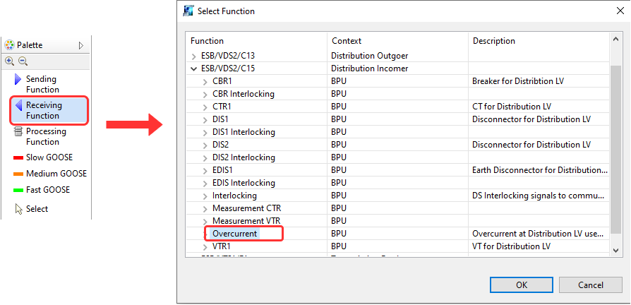
From the palette, click on “Receiving Function“ and click on the screen. A window opens and you can specify the subscriber. Choose “C15 Overcurrent“ function as the subscriber.
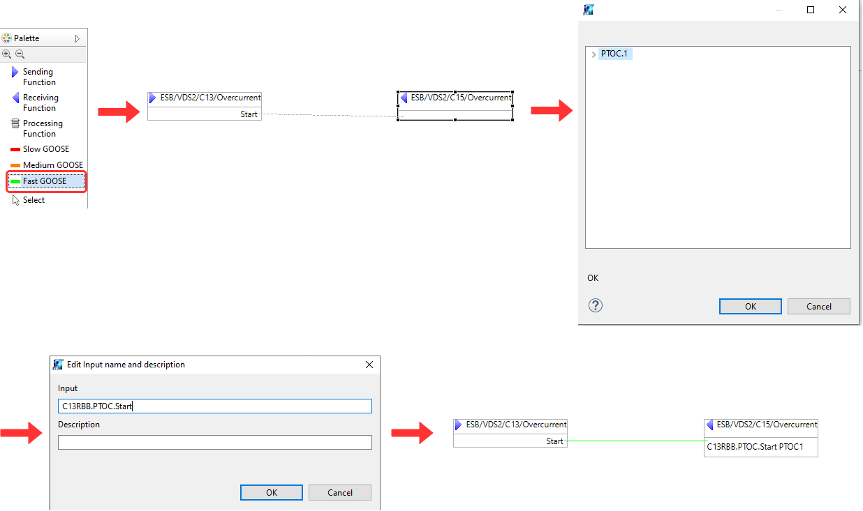
From the palette, choose “Fast GOOSE“ which is the color green and draw a line from “Start“ form C13 to the C15 function. A window opens which asks you to specify which logical node should receive this signal. Choose PTOC. In the next window, write “C13RBB.PTOC.Start“ as the name of the input signal and press OK.
Import ICD Files
From the Dashboard, click on the “Import“ option to import SCL files to the system.
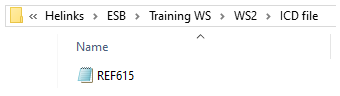
You will asked to import an SCL file. For this project, you need to import the ICD file for the ABB REF 615 IED. So, move to the folder “Helinks\ESB\Training WS\WS2\ICD file” and choose the only ICD file to import which is the REF 615.
The import SCL files window opens. In here, it is shown what type of file you are importing and also what choices do you have with each type of file. For instance, if you are importing SCD files with multiple IEDs, you can choose to import a few of them, or if you are importing files with the substation section, you can choose to import the substation structure. Since you are importing an ICD file now and the IED name is template, the “template“ section is highlighted for you. Press ok and another message should show you that the import has been done successfully.
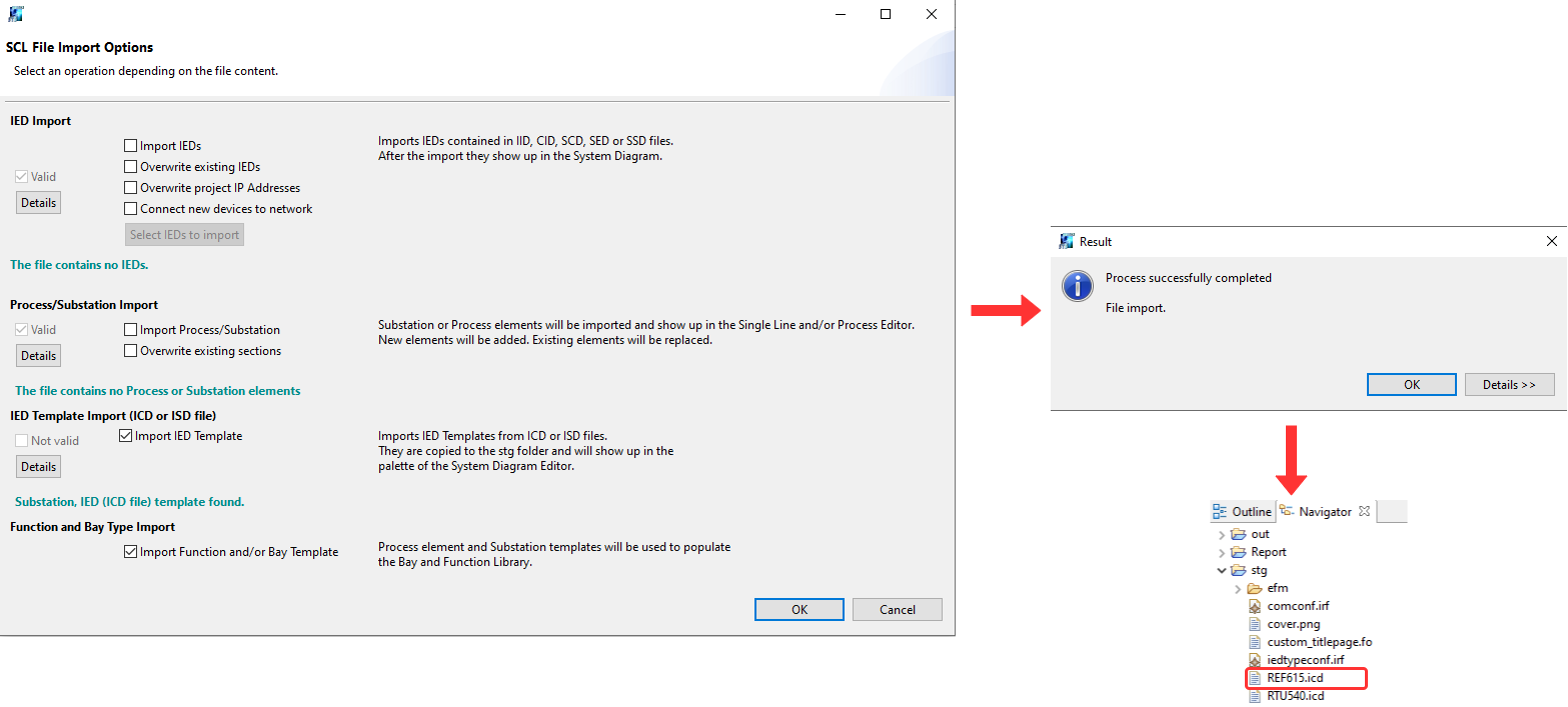
As the figure shows, once the import is finished, you can view the ICD file in the “stg“ folder of the workspace.
System Diagram
System diagram in Helinks STS houses the SCL files which are imported and users can instantiate ICD files and specify the IP addresses for the IEDs. Users can also do some network configuration such as adding switches or specifying network redundancy protocols.
For this training, the REF 615 IED which you have imported should be instantiated since it is from an ICD file and it should be connected to a switch.
Open System Diagram from the dashboard by clicking on its icon.
You can see in the System Diagram, switches are already made for transmission and distribution sections and IEDs are named and have their specific IP addresses according to the tables which can be found here for Distribution and here for Transmission.
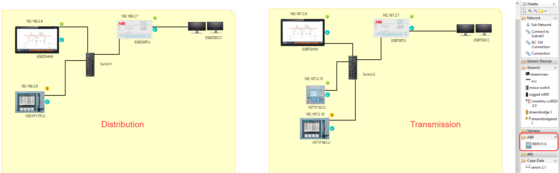
On the right hand side, you can see the palette. From there, you can choose to add generic devices such as switches, empty IEDs, or you can add devices from IED manufacturers such as ABB. The ABB tab has the REF 615 IED which you have just imported.
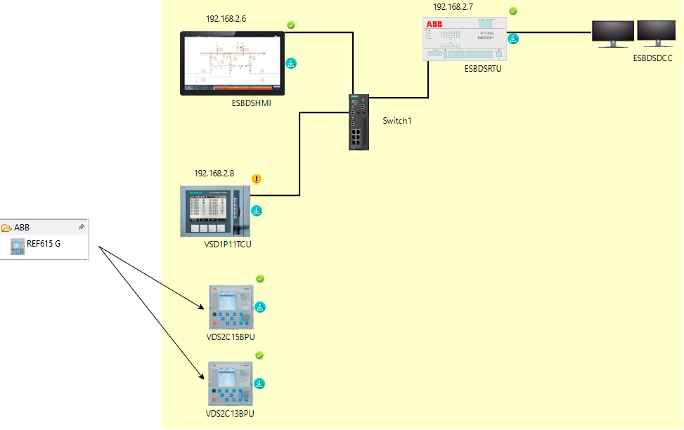
Choose REF615 G from ABB by clicking on it. Then click on the screen on the Distribution side. This instantiates the IED and adds it to the workspace. The name of this IED should be “VDS2C15BPU“ according to the following table, Table 1. Do the same procedure again to add another IED and call it “VDS2C13BPU”.
Table 1: Distribution side IP address
IED name | IED manufacturer | IP address |
|---|---|---|
VDS1P11TCU | Siemens A8000 | 192.168.2.8 |
VDS2C15BPU | REF 615 | 192.168.2.9 |
VDS2C13BPU | REF 615 | 192.168.2.10 |
ESBDSRTU | ABB RTU 540 | 192.168.2.7 |
ESBDSHMI | Zenon | 192.168.2.6 |
From the palette, under Network, choose “Connect to Subnet1“. Then draw a line from VDS2C15BPU to the switch, “Switch 1“. This way, you can set up an IP address. Choose the IP address for this IED which is highlighted in Table 1 which is: 192.168.2.9.
Do the same procedure for VDS2C13BPU and connect to Switch 1 with the IP address 192.168.2.10.
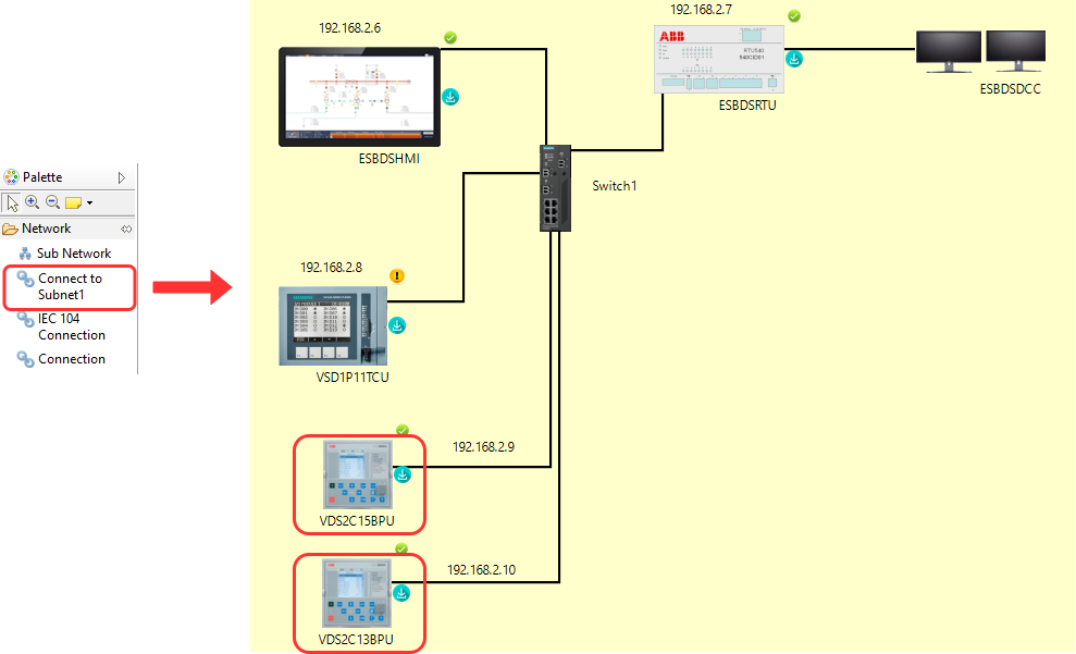
Now both IEDs are instantiated with the correct IP address.
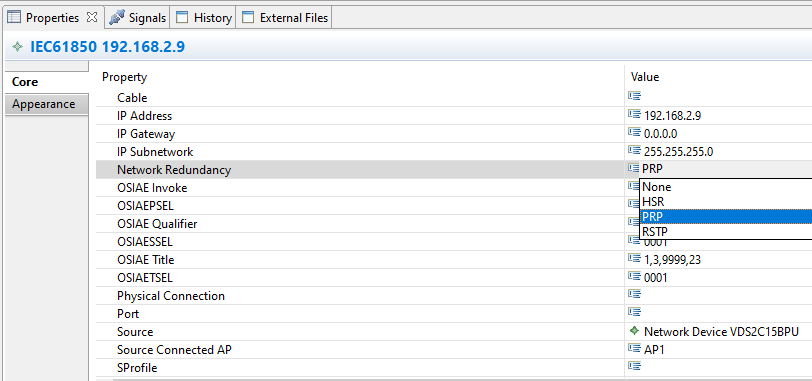
Click on each connection from the IED to the switch and view the Properties at the bottom of the screen. One of the options is “Network Redundancy“. You can set it to HSR or PRP. For this training, set it to PRP.
This is the end of session 2 of the training.
Achieved Goals
Specified a GOOSE application.
Imported an SCL file.
Instantiated IEDs with the correct name and IP addresses.
Specified Network Redundancy.