Single Line Diagram
Selecting the Single Line Diagram in the Dashboard will open up a new main editor window tab next to the dashboard. In the Single Line Diagram you can create Substations, Voltage Levels, Bays, Busbars, and Power Equipment. You can also connect Power Equipment to other Power Equipment and to Busbars.
To create Functions, Logical Nodes, and virtual IEDs, open the Function Specification Diagram of a Substation, Voltage Level, or Bay.
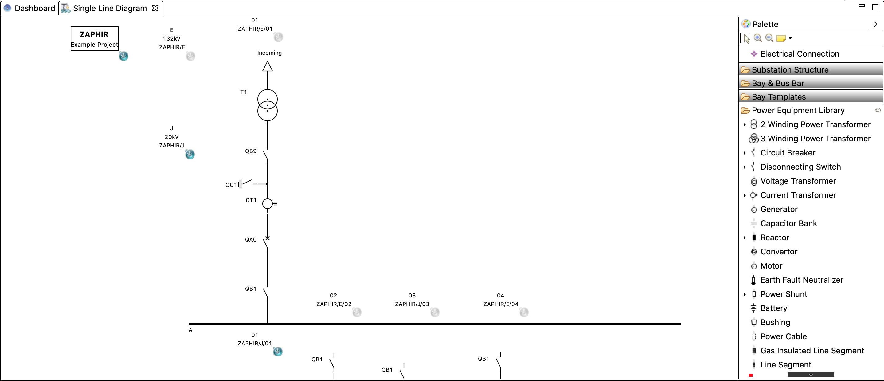
Single line editor
Palette
Electrical Connection
Connection tool used to draw electrical connections between Power Equipments and from Power Equipment to Busbars.
Substation Structure
Contains entries to create new Substation and Voltage Level elements
Bay & Busbar
Contains entries to create new Bay or Busbar elements
Bay Templates / Bay & Bus bar Templates
Contains all available Bay or Busbar templates that are in the currently active library and whose context matches the currently selected Voltage Level element.
Power Equipment Library
Contains all available types of Power Equipment, including types from the currently active library. Power Equipment from the library, and predefined subtypes of certain equipment, can be found by expanding the small arrow on the left of an entry:
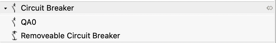
Power Equipment of type ‘Circuit Breaker’, a breaker type ‘QA0’ from the library, and a subtype ‘Removable Circuit Breaker’
Drawing a Single Line Diagram
Creating elements from the palette
Elements can be created by clicking on their entry in the palette, and then clicking on the canvas.
Use left click to select the element in the palette and another left click to add it on the canvas. Drag and drop isn’t available here.
Since SCL is structured hierarchically, this structure is also reflected in STS - there is an ID field shown on Voltage Levels and Bays that displays the hierarchical path.
When right-clicking an element, the ‘Select children’ entry will also highlight all elements that are proper children of the selection.
There is also an icon in the lower right corner of structural elements. A blue icon indicates that this element is currently active. Selecting an element will turn it and its parents active:
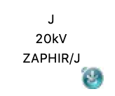
The voltage level 'J' is part of Substation ZAPHIR. The blue icon in the lower right corner indicates it is currently active. New Bays and Bus Bars will be added to 'J' while it remains active.
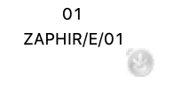
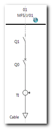
The Bay ‘01’ is a direct child of voltage level ‘E'. It is not currently active - to add equipment to '01’, it first needs to be selected.
Newly created elements will be added to the currently active element of the appropriate hierarchy level.
Voltage level and Power Transformers are added to the active Substation
Bays, Bus Bars to the active Voltage Level
Equipment other than Power Transformers are added to the active Bay or Bus Bar
Make sure that the correct element is active before adding Voltage Levels, Bays, Busbars, or Power Equipment
Drawing electrical connections
Using the “Electrical Connection” tool from the palette allows connecting power equipment with each other and with Busbars.
Electrical Connection
When connecting more than two elements with each other, first draw a connection line between two elements and then connect the next element with the already existing connection line.
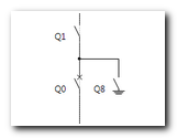
Electrical Connection with more then 2 connection points
Hold down the CTRL key when releasing the mouse button to keep the connection tool active, and keep drawing the next connection.
Relevant Views
Below the main editor window, there are several other views that are relevant to the Single Line Editor:
Selecting elements in the main window will update the content of these views to display additional information on the selected item.
Relevant Element Properties
The Properties view shows additional attributes of the selected element and allows editing some of them.
Substation
Property | Description |
|---|---|
Description | A description of the substation that will be displayed in the element box on the canvas, below the name. |
Name | The name of the substation |
Voltage Level
Property | Description |
|---|---|
Description | A description of the voltage level |
Name | The name of the voltage level |
Voltage | Voltage specified with valid SI prefix (typically kV) |
Num Phases | Number of phases |
Nom Freq | Nominal frequency |
Bay/Busbar
Property | Description |
|---|---|
Description | A description of the bay or busbar. |
Name | The name of the bay or busbar. |
Power Equipment
Property | Description |
|---|---|
Description | A description of the power equipment |
Name | The name of the power equipment |