Configure Signals
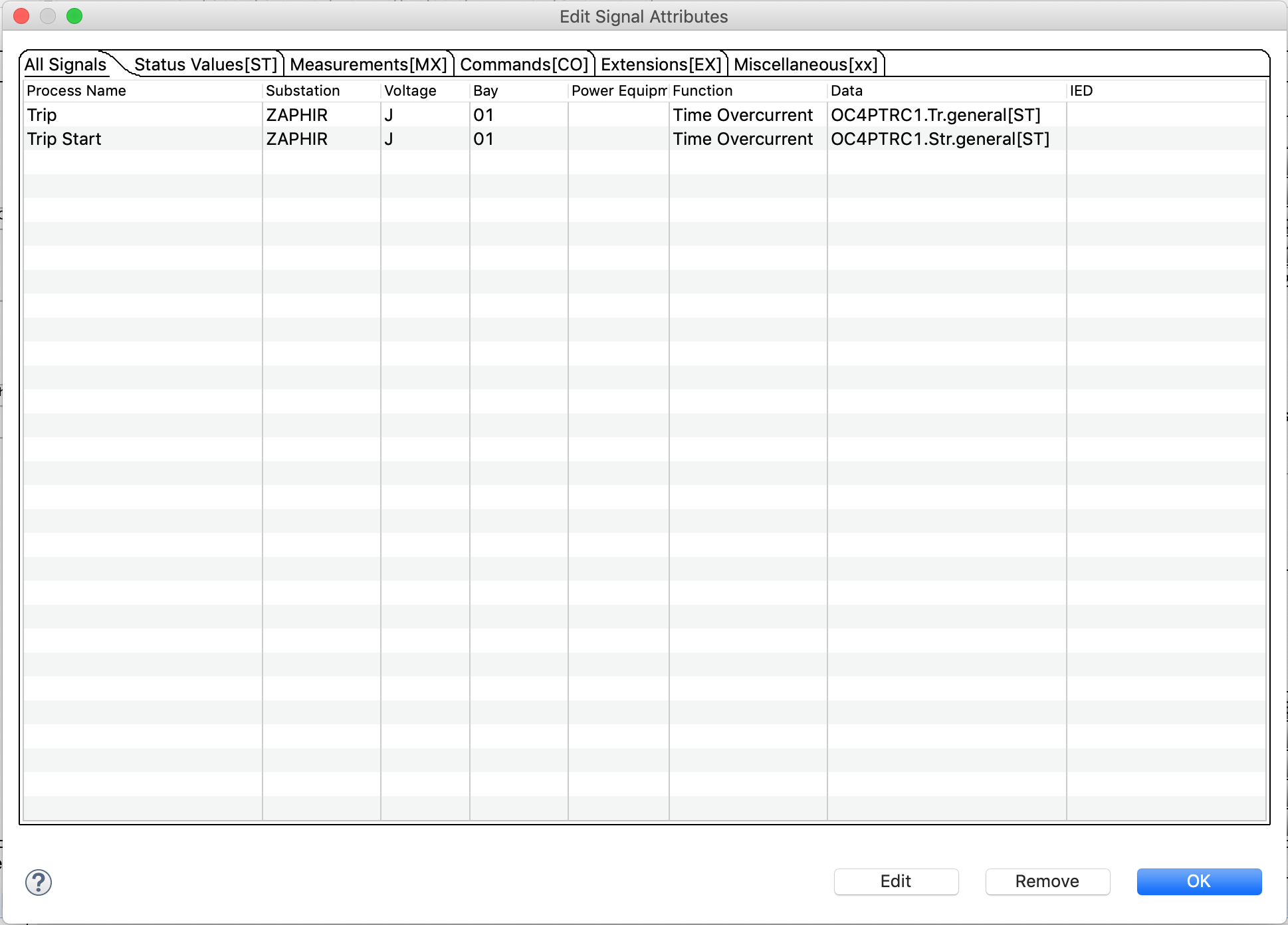
Signals represent outbound data that is selected for communication in the current project. They show up in the Signals view and can be created and manipulated with the ‘Configure Signals’ context menu entry. The “Edit Signal Attributes” dialog will show a list of all the Signals that are currently selected.

Edit Signal Attributes dialog
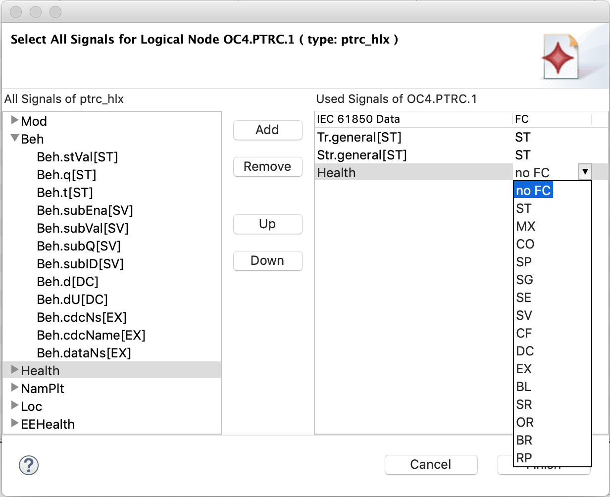
Additional Signals can be selected using the ‘Edit’ button. The tabs at the top of the dialog allow filtering of the Signals according to their functional constraint - this also affects the available Signals when editing.

Configure signals edit dialog
In the ‘Edit’ dialog, the left side shows which data attributes are available for the chosen logical node, according to its type definition. The logical nodes created from the default palette usually contain all optional data attributes. When binding a logical node to an IED, the type will change to the logical node type provided by the device manufacturer. Accordingly, the list of available data attributes will reflect the new data type. Signals are always defined on the lowest data attribute level. If you select a data object or structured data attribute, all contained data attributes will be added to the Signal list. You can select a specific functional constraint for a DO ( see the drop-down menu next to ‘Health' ) to only add matching signals.
Since the available data attributes may change when binding a logical node to an IED, previously defined Signals may use data that is not available in the implementing device. Similarly, when importing Signal Lists from Excel, data may be specified that is not actually available according to the logical node type. In such a case, the Signal will have a status of ‘Unresolved’, and the logical node will have an engineering status of ‘Error’ until all unresolved Signals have been fixed or resolved. See <Signal List> for more details.
