Mapping logical nodes
A Function connected to a virtual IED implemented by a real device is said to be implemented by that device. However, this connection is not sufficient to determine all implementation details. IEDs often contain many logical nodes of the same class - which of these logical node should implement a given functionality requires engineering knowledge.
Double-clicking on ( or selecting ‘Map Logical Nodes’ from the context menu ) a mapped virtual IED brings up a mapping dialog that allows associating logical nodes from the specification with logical nodes in the implementing IED.

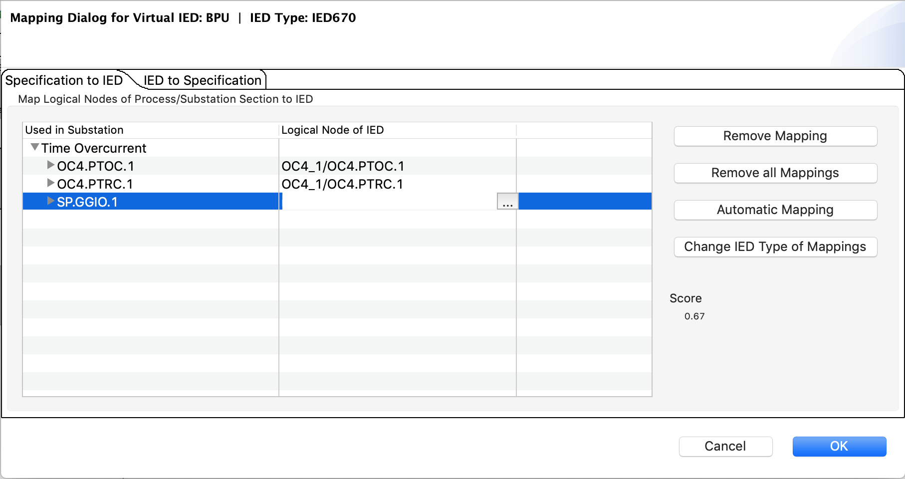
Specification to IED Mapping dialog
In the mapping dialog, a list of all logical nodes associated with the virtual IED is listed in the column ‘Used in Substation’, with their assignment to the real device shown in the column ‘Logical Node of IED’. Clicking on the corresponding entry in the second column shows a selection dialog:

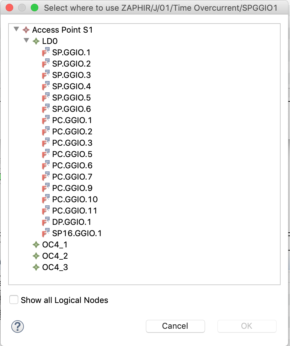
Specification to IED selection dialog
Here, a filtered view of the data model of the IED is shown. Unless ‘Show all Logical Nodes’ is selected, only logical nodes of the same class are shown. Selecting a logical node and pressing ‘Ok’ will establish a mapping between the selected logical nodes of the real device and the specification.
Logical nodes may be mapped to different classes - this is usually only required if the IED supports the desired functionality, but does not use standardized IEC61850 data for it. The mapping indicator for logical nodes mapped to a different class is a red closed chain.

LN mapped differently
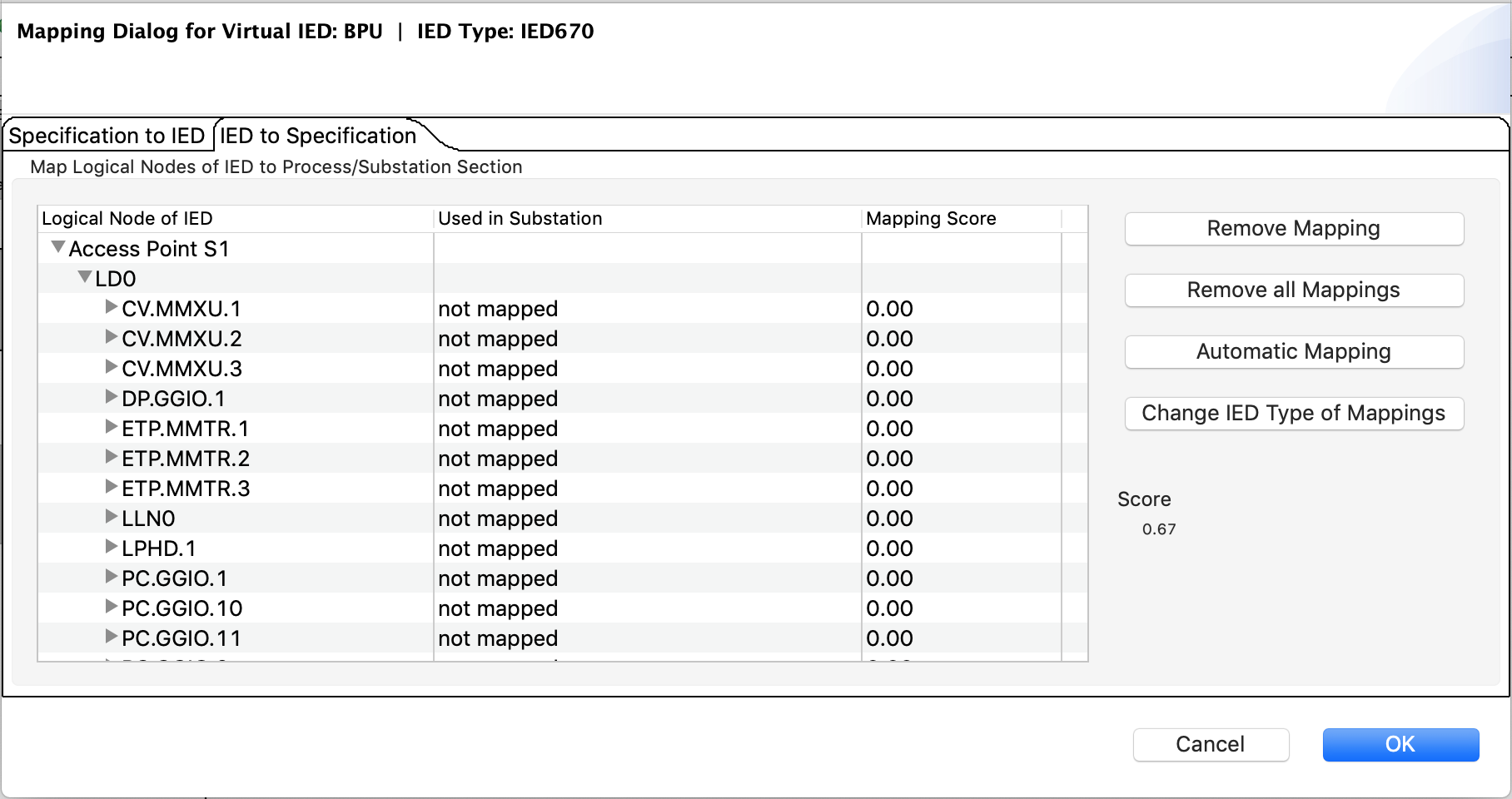
Sometimes, there may not exist a 1-to-1 matching of logical nodes in the specification and in the device. In this case, additional logical nodes can be brought into the function, using the ‘IED to Specification’ tab of the mapping dialog.

IED to Specification Mapping dialog
In this mode, the entire data model of the IED is shown, together with its use in the specification.

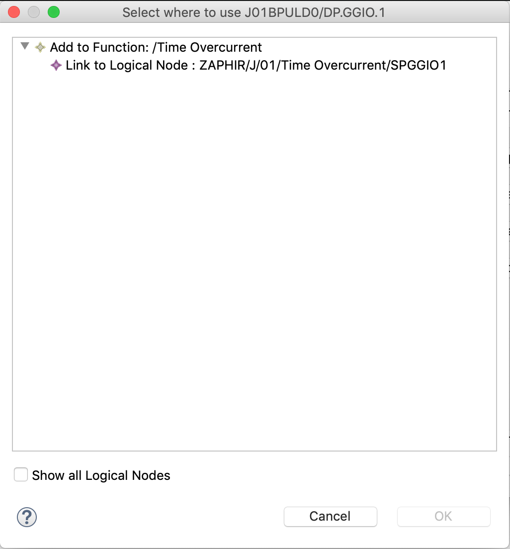
IED to Specification selection dialog
The dialog to establish a new mapping has an additional functionality. The selected node in the IED may also be added to any of the connected functions by selecting the “Add to Function:” option. Logical nodes that are created in this way will be marked as “Implementation only” in the property sheet, and the mapping status indicator is a yellow closed chain.

LN implementation only
