Editing application templates
After you create a templated application from either transforming an existing basic application, or instantiating it from the library, there will be a corresponding item in the application view .
Double-clicking on that item (or selecting Open Template Editor in the items context menu) will bring up a diagram editor where you can inspect and edit the structure of your application template.
Diagram editor
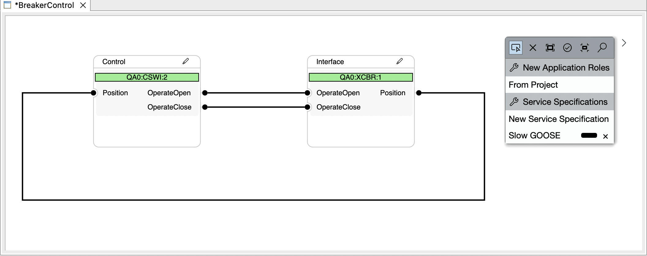
The ‘Breaker Control’ example application template
The diagram editor consists of a canvas with a single type of node, called a root application role(in this example ‘Control’ and ‘Interface’). They have an internal structure with subelements that can be connected to each other, with each connection belonging to one of the service specifications of the application. Application roles are the main interaction element when using a finished application template, and editing them and their connections is the main purpose of this editor.
An important part of the editing process is the ‘Properties’ view, by default present in the view stack in the lower right corner. Here, more detailed information on the selected elements can be seen and edited:
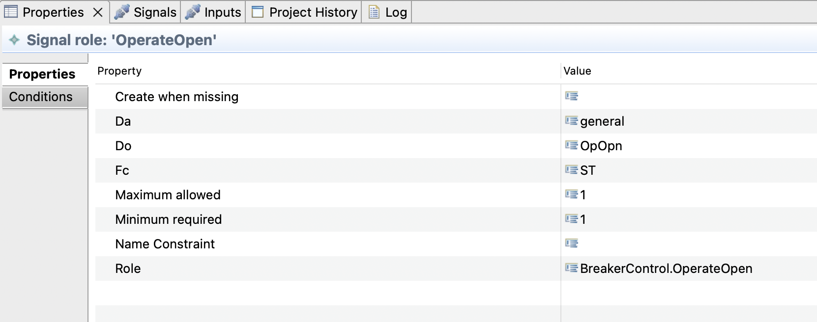
The Properties of the ‘OperateOpen’ signal in Control/QA0:XSWI:2
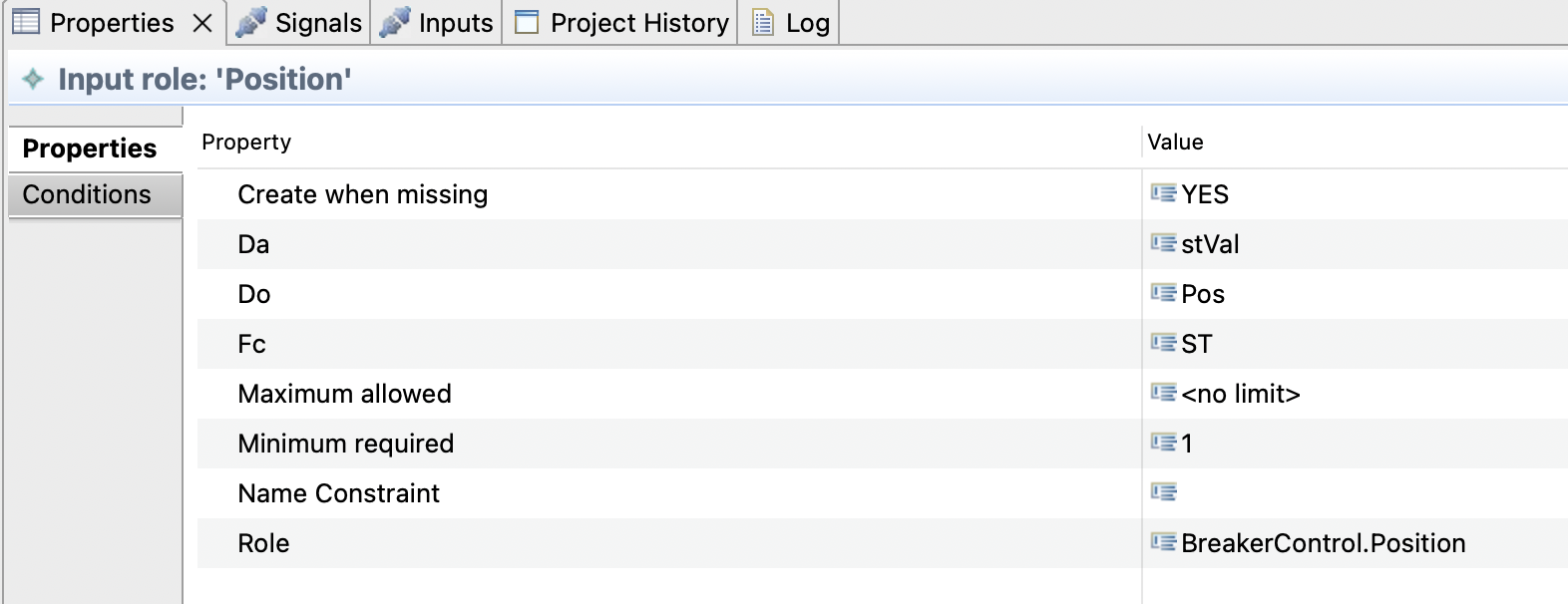
The Properties of the ‘Position’ input in Control/QA0:XSWI:2
The palette to the right can be used to create new root application roles, new service specification, and to draw new connections using the service specification as a tool. Currently, there is only one way to create application roles, “From Project”, which uses an existing function as a base. Future releases will offer more options.
Application roles
Even though root application roles are created from functions when transforming a basic application into a template, it is important to stress that application roles are NOT functions!
Instead, they describe the attributes, properties and content a function must possess in order to be usable by the application template. The requirements on the content are distinguished by the type they describes, of which there are 4 important categories:
Logical Node Role
are the main structural elements of a root application role, shown as a box with green background, similar to their appearance in the function specification. Their content (signal and input roles) are drawn in a light grey box.Signal Role
contained in a logical node role, aligned to the right side, with a small dot extending outside the root application role to indicate where connections originating from this signal can be startedInput Role
contained in a logical node role, aligned to the left side, with a small dot indenting the root application role to indicate end points for incoming connections.Every other role
Every other role (typically nested subfunctions or subequipment) serves as a structural element to identify the location of a logical node, but typically has very little impact otherwise
To relate to the ‘BreakerControl’ example above, in order for a function to be compatible with the application role ‘Control’, it must contain a logical node (directly, not in a subfunction) of specified class ‘XSWI’, with a specified prefix of ‘QA0’ and specified instance number ‘2'. In this logical node, two signals are required, using the IEC 61850 data OpOpen.general and OpClose. This description is not exhaustive - a function may contain any number of other logical nodes or subfunctions that are not relevant to the 'BreakerControl’ application template.
New Application role from Project
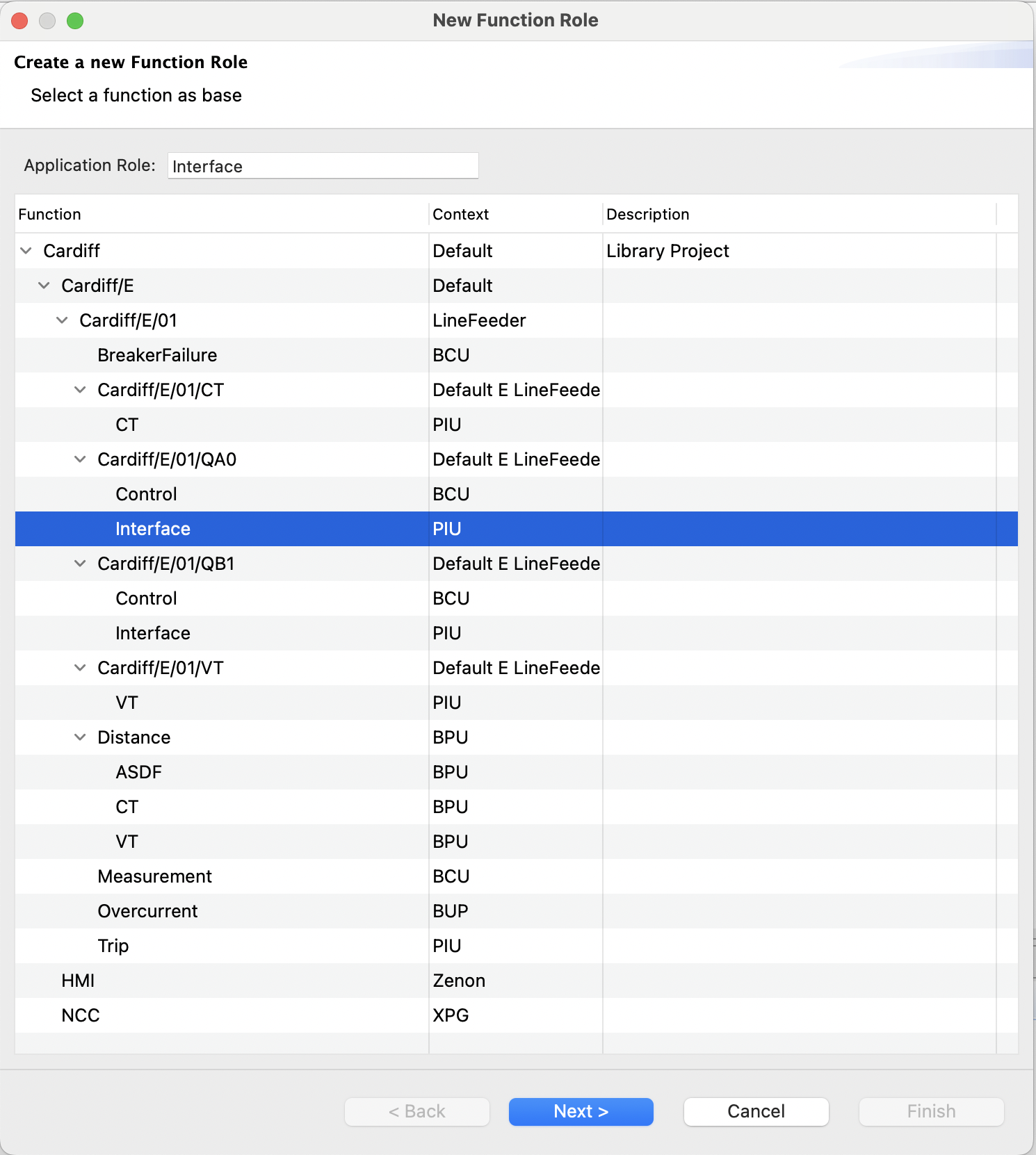
Using this creation tool from the palette opens a wizard that helps setting up a new application role. In the first wizard page (base element selection), a tree representation of the current project is shown, and a single element must be selected. The selection serves as the basis from which the application role is created.
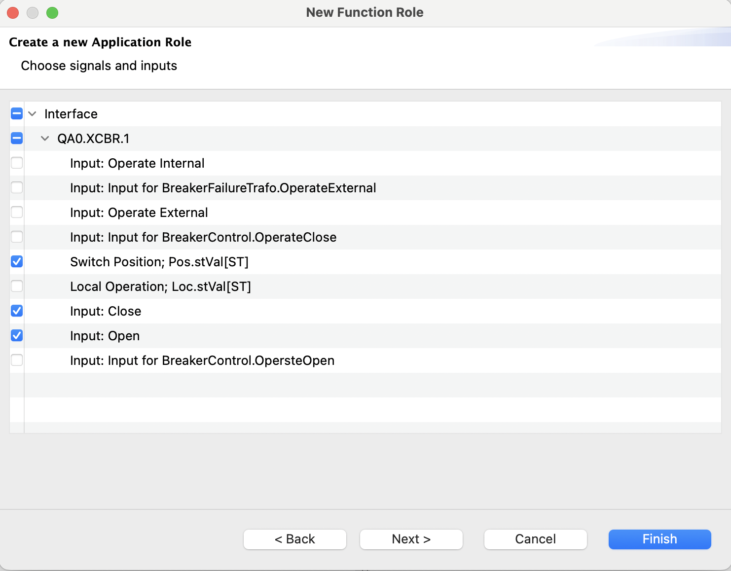
In the second page (content selection), the content of the element selected in the previous page is visible. At least one input or signal must be selected in this page to proceed. All selected elements will be included as descriptions in the application role.
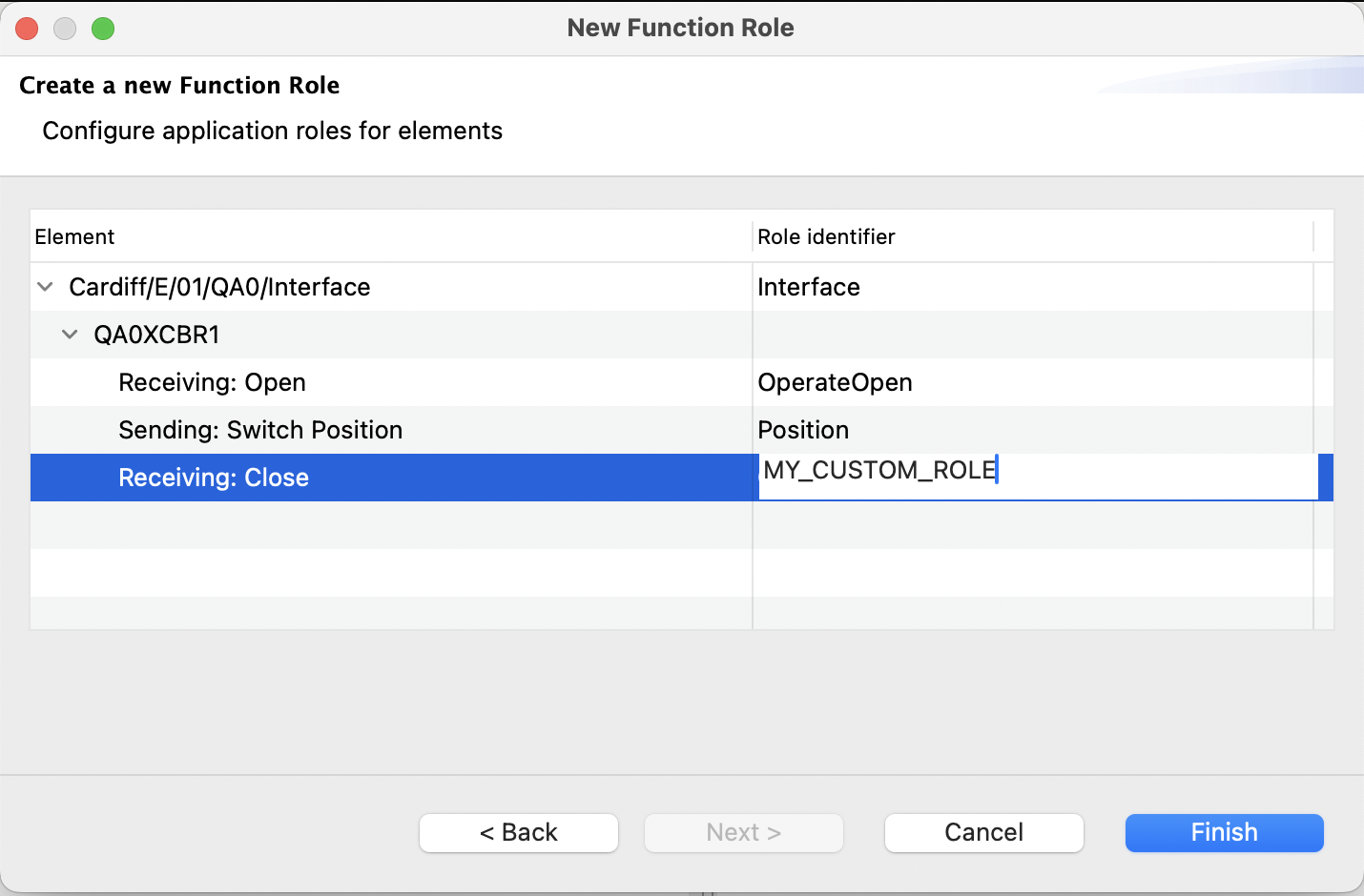
In the optional third page, a tree representation with only the selected elements from the second page is shown. Here, the application roles (as seen in the corresponding attribute) can be edited. Note that application roles are mandatory for the root element, and for the signals and inputs. For all intermediate levels, including the logical node level they are optional and omitted by default.
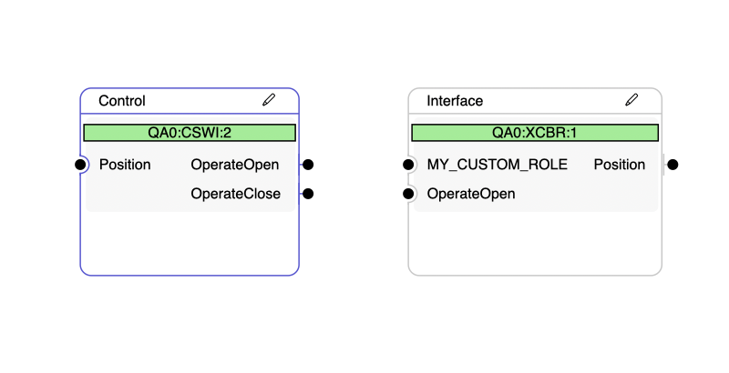
After finishing the wizard, the application role is added to the diagram, and the selected base element is added as a participant.
Editing the content of an application role
In the header bar of each root application role, there is a small button shaped like a pen. Clicking this button brings up a wizard very similar to the “From Project” creation tool, but starting from the content selection page (as the root element is already fixed).
Unchecking signals and inputs here will remove them from the application template, while checking previously unchecked signals and inputs will add them in the same way as in the creation tool.
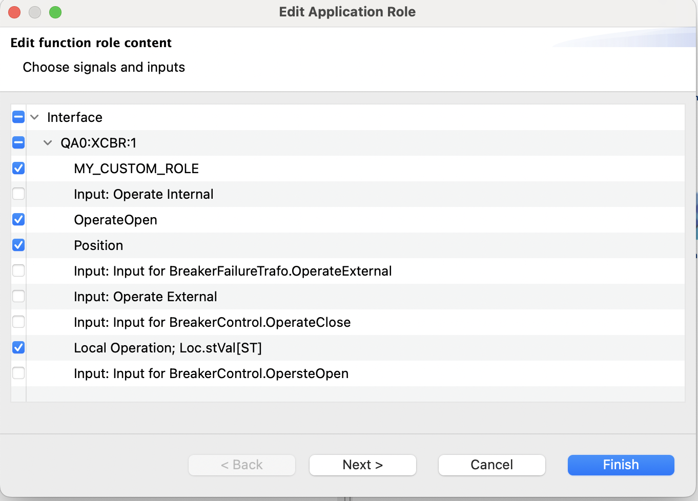
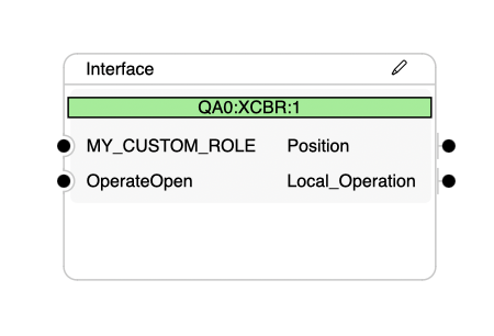
Editing the previously created application role - checked ‘Local Operation’ as well
The content displayed is the aggregate content of all the participants that are assigned to this application role. If no participant is assigned to the application role, no new inputs and signals exist that can be selected.
Noteworthy properties
The property sheet distinguishes between two main groups. Generic properties are in the main tab “Properties”.
Additional conditions are visible and editable in the tab ‘Conditions’. These are typically constraints on further attributes such as the process name of a signal or the prefix, lnclass and inst of a logical node.
Role
All elements have the role attribute, a string identifier prefixed by the application templates profile id (e.g. ‘BreakerControl.Control’). This element is mandatory for the root level, and for signal and input roles (although the later condition may be relaxed in future releases). A role identifier must be unique within a main application role. There is an exception due to previous usage for signal and input roles - they are considered independently for uniqueness.
Example: a signal role with role='BreakerControl.Position' may coexist with an input role with role=‘BreakerControl.Position’, but not with any other type (logical node, function, etc.).
Name constraint
Name constraints are highly recommended to use when a subfunction hierarchy is modelled (and are set by default in such a case). They always allow the application template to uniquely identify the correct element, since the name is unique at every hierarchy level. Omitting a name constraint may still result in a unique identification due to other conditions (e.g. Phase in a SubEquipment, description, or any other attribute), or by virtue of there being only a single candidate of the correct type present.
For historic reasons, the name of a signal is composed of the IEC61850 data reference (i.e. DO.DA[FC], and not the process name as shown in the signal table. The process name can also be used as a constraint in the ‘Conditions’ tab of the property view!
DO / DA / FC
These attributes are only present on signal and input roles and correspond to the IEC61850 data reference (data object, data attribute and functional constraint). For signal roles, these restrict what IEC61850 data the signal is sending. For input roles, these constraints record the pDO, pDA values that are present in ExtRefs used for later binding. However, the selection of ExtRefs does not yet support filtering according to preferred values, but the data fields are already present to be forward compatible with future versions of the tool.
Create when missing
This field can be set to allow the application template to create inputs on demand, i.e. when an input is required but no free inputs are available. Creating an input will use the name constraint as name, with an added suffix ‘_#001' if already taken. Creation will respect the 'maximum allowed’ attribute and only create up to that number.
Maximum allowed
This value governs how many elements can be assigned to this role. The default value is '1' for all element types, except inputs that have no limit.
When using the default parameters, there will typically only be a single assignment per role done automatically. However, explicit assignment by the user or changes to the application template may lead to a situation where more than one element is assigned. Increasing the value of ‘maximum allowed’ will tell the application that this is a valid configuration and to not raise an error.
Minimum required
This value governs whether an element must be present in the application. By default, all defined elements must be present. If some signals should be used when present, but are allowed to be absent, consider setting this value to ‘0'. Values higher than ‘1’ are also possible to enforce multiple assignments, and the 'maximum allowed’ should be changed accordingly.
Creating connections
The palette contains a segment titled Service configurations. Each of the entries here is a connection tool that can be used to link signals and inputs with each other.
Selecting a service specification tool allows you to click on the circular port to the right of a signal and then again on the circular port to the left of an input in a different application role to create a connection between the two. It is also supported to drag from signal to input without releasing the mouse button.
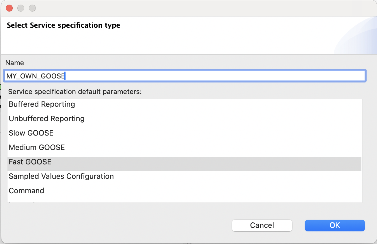
Create a new specification by choosing name and default parameters
Doing this with the tool ‘New Service Specification’ will then open up a dialog to create a new service specification. A name can be given (must be unique), and a set of initial parameters must be chosen. The service parameters can be changed later from the application view, but the service type is fixed.
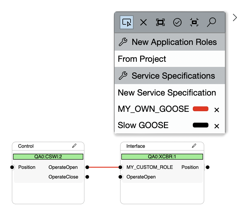
Clicking on the small colored line on the connection tool will bring up a color picker. Lines will use the selected color. The 'x' to the right of the color picker will delete the service configuration along with all the lines in it.